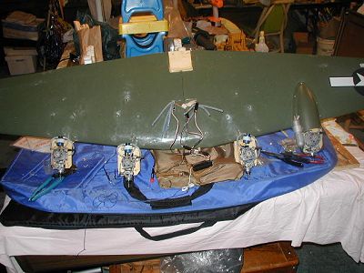
Four Engines and Only One Fuel Tank
Paul of RCWARBIRDS has once again sent this lowly reporter out into the world of RC in the never-ending search a better way of doing something, and this is that story.
There have always been numerous questions and opinions about how to service multiple engines with only one fuel tank. I personally have not been able to add much to these discussions, as I have never gotten it to work. Reliability is always of prime importance in such applications, due to dire (Defined as expensive, in the dictionary) consequences of an engine failure. As the number of engines grows, the investment in time and money skyrockets exponentially.
Yes, I have tried one tank and two engines.
Using tees on the outlet’s leads to sucking air if one engine is not running.
Using separate outlets and muffler pressure leads to a flooded engine on the non-running engine.
Muffler pressure will not safely send fuel over a few inches, which is little to no use on a scale warbird.
I will still go on record as recommending using separate fuel tanks located behind each individual engine and individual servos for throttle control to keep things simple.
For some reason, I get calls to test out prototype ARF’s of other people’s design. Let’s see, only one such plane in the world and you want me to build and test fly?? Not my plane, sure, why not!!!! Then Paul beats me to death to get the review to him.
Recently, I had the opportunity to evaluate, (Covered in another story) a prototype ARF B-17. Due to the design of the initial prototype, there is no way to install individual fuel tanks in the nacelles or wings of this plane, without cutting up and destroying the scale lines of the wing. NONE!!! (I will add at this time, the manufacturer is in the process of redesigning the engine mounts and nacelles to correct the problem before market introduction. This process is too expensive and complicated for an ARF, I do not care what model it is!!!)
Always up to a challenge for the glory of RCU and the twins forum, I decided to see if past ideas and suggestions would actually work to supply four engines from one tank located in the fuselage and on the C.G. to minimize balance shift as fuel is burned off during flight. (Note that twin sanity is a primary response to flying multiengine aircraft.)
What have I got myself into??
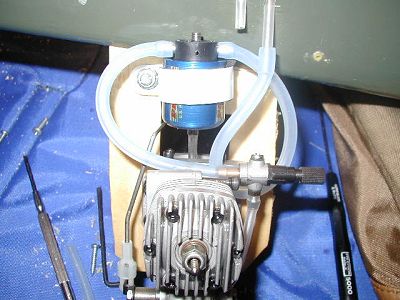
First step. How to supply fuel to individual engines over long distances, in this case up to 18” from the fuel tank? I have used Perry VP30 pumps in engines up to the ST 4500, but was not sure they would work on .25 to .35 size engines. I planed to use Magnum .32 engines to use the scale 8x6 three blade props. (Ok, so it is over kill on engine size, but it is my story and I am sticking to it!) Off to the L.H.S. for one Perry VP30 pump and set it up on the test stand. Note, this pump requires that the crankcase be drilled and tapped for a pressure nipple to power the pump. Do not get the oscillating pump that works on vibration or VP-20. It will not work well on two strokes and have no experience on four strokes that it is intended for. You also do not use muffler pressure at all, so the muffler nipple is removed and sealed to cut down on the mess.
Set it up on the test stand and tried it out. Yes, it works, but the pump fuel pressure was reduced, via the regulating screw, by one turn. DO not turn this screw out too much or the internals could be damaged and the pump is not serviceable. I found the idle screw on the carburetor needed to be screwed in by ¾ turn and the high-speed screw by up to on full turn in or to the lean side. Do not use an air bleed carburetor for this fuel pump arrangement. It will not work on idle. You need to control fuel flow, and not air bleed. So much for the OS LA engines!
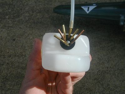
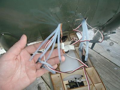
Step Two (Problem two) How to get separate feeds for four engines, and don’t forget fuel and vent lines. Solution. Drill new holes in the inlet nipple of an 18 oz tank, and use five clunks and one vent line. Why five clunks you ask? One for each engine and one for fill and drain. Yes, you heard me six lines coming out of one fuel tank and run around ten feet of fuel tubing and five connections at the wing to fuse connection. I am using one fuel dot on the fuselage to fuel and de-fuel this monster.
Step Three. Drill and tap all the backing plates and install the fuel pumps in series with the incoming fuel lines per the instructions with the pump. Note that the special tubing to the pump from the backing plate should be as short as possible for best pumping action. I found that if I inset a foam piece in the strap for the pump, it does not shift around as much.
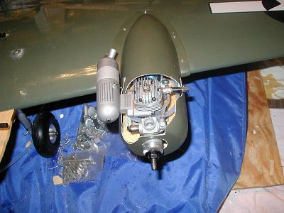
Step Four. Install the engines, pumps, fuel lines, controls, fuel dots, vent lines, connections at the fuselage to the wing connection, and wiring and head to the field. Neighbors will not appreciate the noise of breaking in and adjusting four engines in the local neighborhood.
Step Five. Spend the better part of two hours adjusting, tweaking, using fowl language, wondering how and why I got into this mess, and trying to synchronize four engines, to at least the same neighborhood speeds, response, and performance. I did find that mid range could be adjusted to some degree using the pressure regulator adjustment on the pumps. The most important part of this adjusting is holding the plane straight up and cycling the engines up and down. ANY sag or loss of RPM must be corrected NOW. DO NOT fly if the engines die or even sag. Set the engines to a richer than normal condition for safety. Note, this is also an advantage of slightly larger engines, in that they do not have to be peaked to pull the plane.
Conclusion…..Does it work? You bet. The secret project flew today. If you have a model with no room for tanks in the nacelles, this is one possible solution. I know that there are other possible solutions. If you have an idea, please document it and share with the rest of us.
Twinman
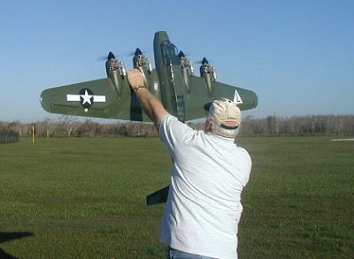
How to break in four engines? Note the lower right one has the pump for initial testing. All of the engines were eventually fitted with the pumps.
|