|
| |
|
| |
|
|
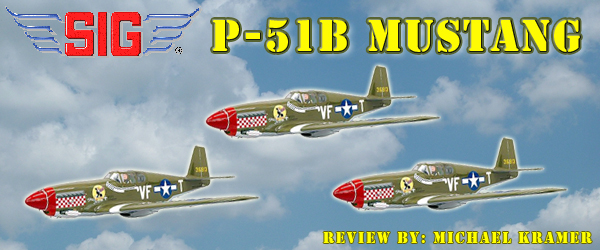
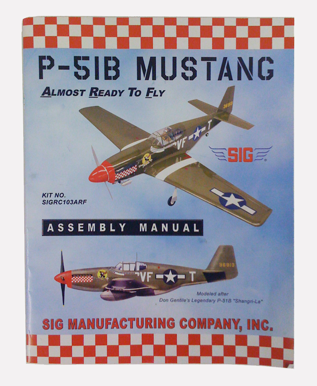
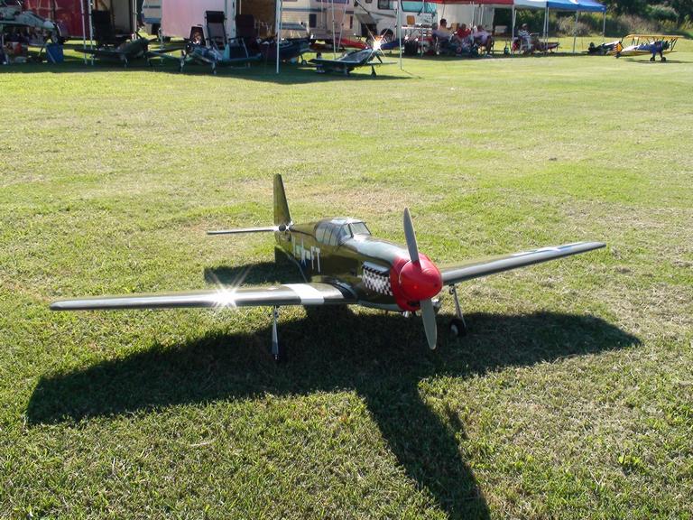
When it comes to the P-51 Mustang, the D model reigns supreme. The B model is not near done as often but is gaining in popularity. Enter Sig MFG P-51B ARF modeled after Don Gentile's famed "Shangri-La". As one of the more famed P-51's this beautiful recreation from Sig Manufacturing will definitely turn some heads at the flying field. The P-51 was originally designed for the British as a replacement for the P-40. When Curtiss unable to keep up with the demand for P-40's, North American Aviation was slated to produce P-40's under license, but instead sold the British on the idea that they could produce a better fighter than the P-40, and that is exactly what they did. As one of the first models to enter combat service the B model was under powered. Equipped with an Allison engine the Mustang was confined to low level ground attach missions. It wasn't until it was matched with the powerful and legendary Merlin engine was the Mustang able to go head to head with the best the Germans had to offer. The instruction manual includes four pages of history on the P-51 and Don Gentile with historic pictures of the "Shangri-La". It is definitely worth the time read but make sure you read the first page before you cut out the templates on the preceding page. |
|
| |
 |
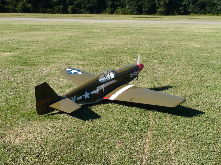
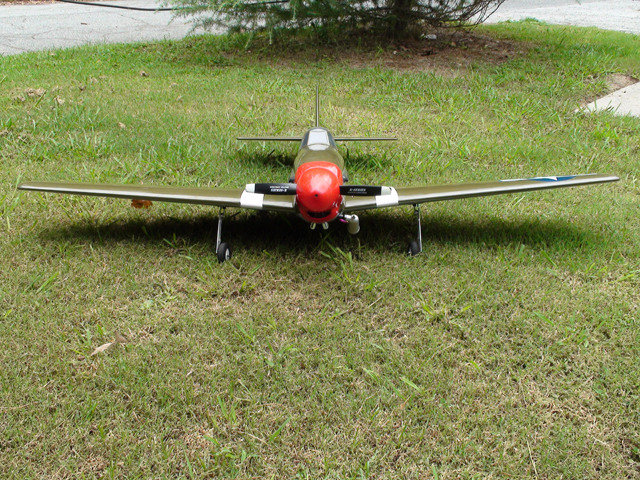
The P-51B from Sig MFG is well crafted sport scale version of the Mustang. It bares all the signature characteristics that make the Mustang one of the most recognized planes in the world. was well packaged and undamaged despite the box being very thinned walled. Opening up the box, I was very impressed with how well the plane was covered. There was not a wrinkle to be found on the entire airplane. It is by far the best covered plane that has been reviewed so far. Inspecting the rest of the kit I found that the overall build quality was outstanding as well. With more and more companies producing ARF's today the level of detail and quality can certainly vary. |
|
| |
The P-51 had all the items one would expect and some others that are not as common. |
| |
|
|
| |
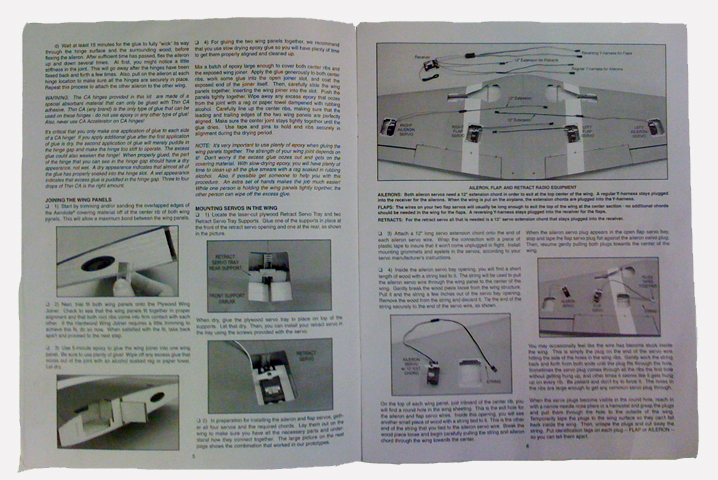
Compared to most ARF instruction manuals the one for the P-51B looks more like a novel as it is 30 pages and goes in to great depth for each step. For a new comer to scale ARF's this manual will be very helpful but if you have a few planes under your belt many of the steps won't ever require looking at. The manual also covers a great deal of history not only on the P-51 but also on Don Gentile's plane the "Shangri-La".
Starting off with the wings both the ailerons and flags were glued in place. The ailerons use CA style hinges while the flaps use pin hinges. For the ailerons, small pieces of card stock were cut into a wedge shape and used to keep the CA hinges centered. Thin CA was then wicked into the hinges from both sides. The flap first had to have the hinge point greased up with a little petroleum jelly before using 30 minute epoxy to glue them in place.
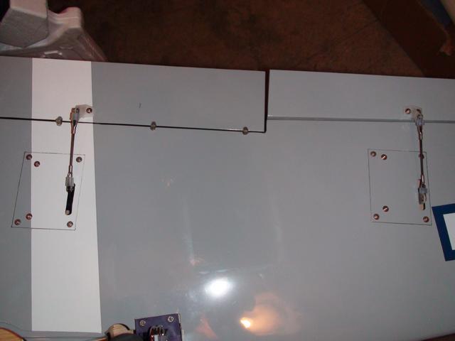
Next the wing halves were glued together with 30 minute epoxy. Here the quality of construction made it very easy to get the halves to line up. Once the wings were dry the retract servo tray supports were glued in with CA at the leading and trailing edges of the retract servo cutout. Then the retract servo tray was glued to the supports with CA as well. The retract servo when then installed for later connection to the retracts.
|
|
|
|
|
| |
|
|
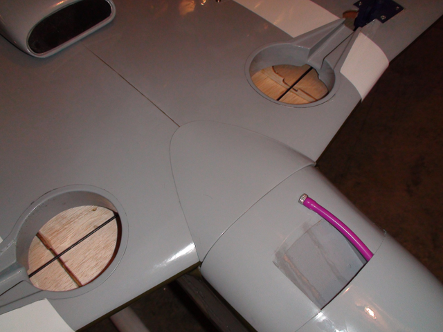
Before the aileron and flap servos could be installed the hatch covers had to be assembled. This is one of those tasks that is just not a lot of fun. It seems crazy that the factory can take the time to put the covering on the hatch but can't add the servo mounting blocks. Of course Sig is not the only manufacturer that does this but at least they understand that this is a weak area and supply screws to aid in securing the blocks. This is when I can really appreciate the molded plastic servo hatches that were supplied with the World Models P-47. Once the servo hatches were completed and the servos mounted they were installed in the wing. Each aileron requires a 12" extension to reach the center of the wing. The flaps require either a reversing Y harness or to be plugged separately into the receiver with one channel reversed.
Attaching the control horns was made much easier by the fact that the linkages were already cut to length requiring only minor adjustment once connected to the servos. There is a difference in the length so take note the longer linkages are for the ailerons and the shorter ones for the flaps. The recommend throws for the ailerons are 7/16" up and down and the flaps are 1-1/2" down max. |
| |
|
|
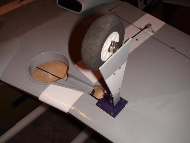
Most ARF's including the Sig P-51B don't come with the gear pre-installed like several of our other review planes have. This is a nice feature that really cuts down on the build time. I expect that will become more common in the future as more manufacturers get into the ARF market. So the installation of the landing gear although straight forward took a little time to complete. The struts first had to be removed from the gear, then bent approximately 7° and cut to length in order to fit in the wheel well properly. Now it would have been nice to have had this done already but Sig includes a template in the back of the instructions that aids in this task. The strut is reassembled and the wing was marking and the mounting holes drilled. The gear is then installed to check the strut position, followed by installing the axle and wheel. The trick part in getting mechanical retracts to function properly is connecting the linkage rods and adjusting for the correct throw of the servo. Again this has to be done by the modeler but the manual provides detailed information and a template that ensures the gear will work the first time. Adding vacuum formed wheel wells and the gear doors complete the landing gear installation.
|
| |
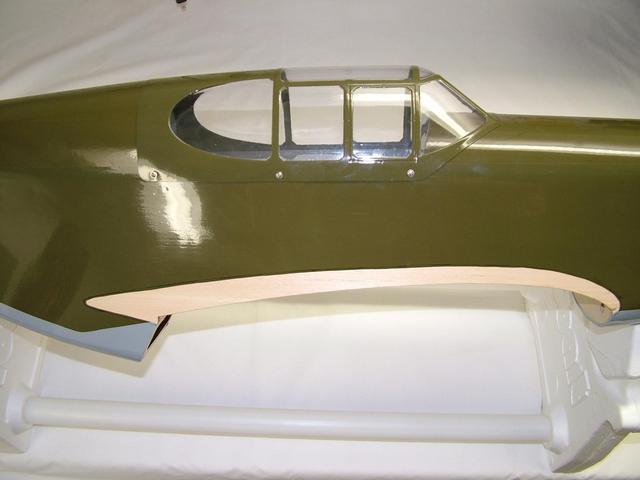
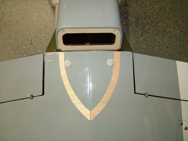
The wing fillets, air scoop and wing LE fairing all have to be installed by the builder. The scoop and fairing can only be done after the wing halves are joined but the fillets could have easily been done at the factory. I'm sure the reason they are not is for shipping purposes but this is a step that I really feel should not have to be done by the builder. The fillets had to first be taped to the fuselage and the outline marked with Sharpie fine tip pen. The covering is removed from the fuselage about a 1/16" inside the marked line. The instructions suggest using a slow drying epoxy to glue the fillets to the fuselage; once the epoxy was applied, the wing had to be bolted in place to position and hold the fillets while the epoxy dried. Wax paper was sandwiched between the wing and fuselage to keep the excess epoxy from oozing onto the wing. I found that using the epoxy did not bond very well and not long after the fillet started to come off. In the areas where the fillet was separating I wicked some thin CA to improve the bond. I found the CA to be a better choice for this task.
|
| |
|
| |
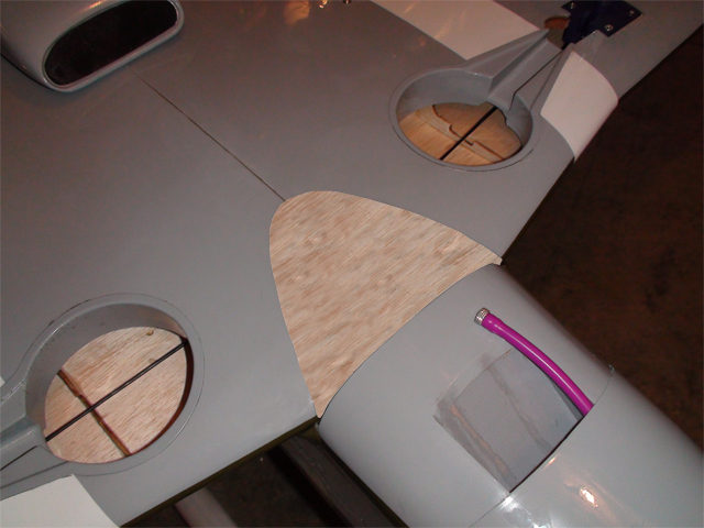
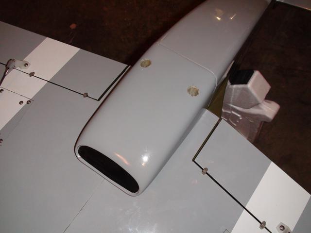
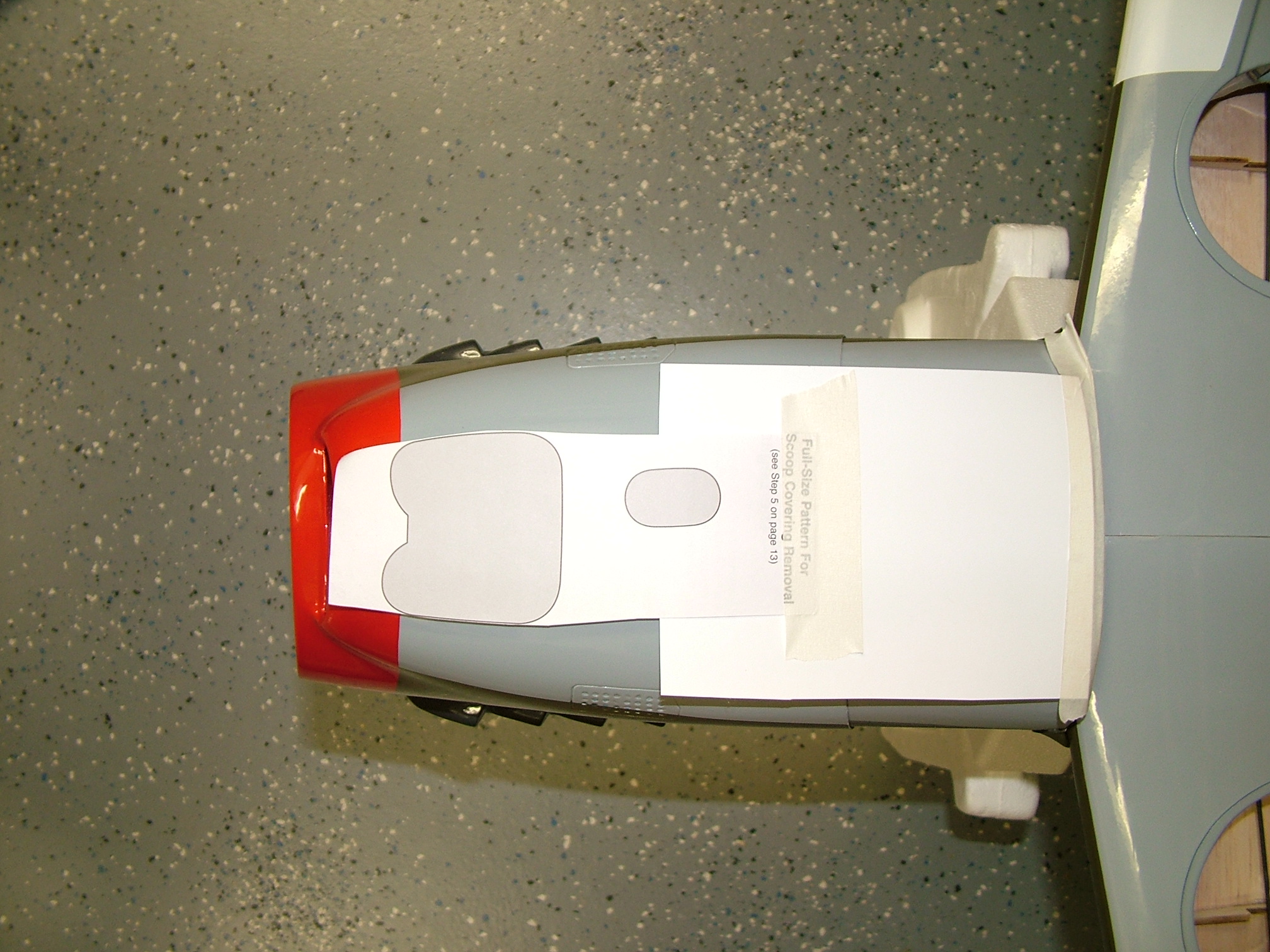
The wing LE fairing is attached in the same way the fillets were but I used CA instead of epoxy. The air scoop also needs to have the covering removed before gluing but this time a template provided in the back of the manual is used for marking where the covering is to be removed. Wing bolt reinforcements had to be glued first to the wing before securing the scoop and the scoop had to have holes cut in it so it could accept the wing bolt guide tubes. With this done it was time to glue the scoop in place, again using CA. Once the scoop was secure the wing bolt guide tubes were slipped in the holes previously cut in the scoop and slide over the wing bolt reinforcements. The tube was then glued to the scoop and reinforcements with thin CA. Lastly the guide tubes were trimmed and the wing was complete. |
| |
|
| |
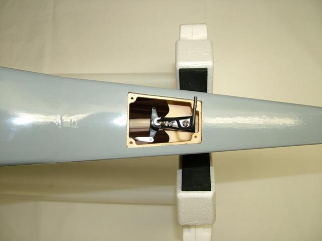
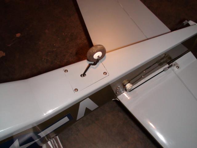
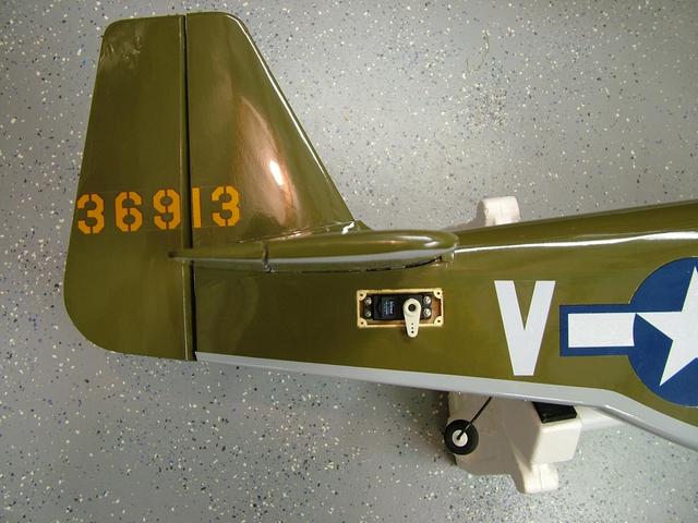
It was time to move on to the fuselage. The tail wheel which is located about half way between the TE of the wing and the rudder is accessed by a hatch. This was a nice touch as all too often ARF's just stick the tail wheel to the rudder regardless of where it was on the full scale plane. The tail wheel came pre--assembled so all that needed to be done was to attach it with two small screws. Before securing the hatch the tail wheel pushrod which is shorter than the rudder pushrod had to be attached to one arm of the tail wheel tiller. Installing the rudder servo and attaching the pushrods were the last step before starting on the tail assembly. |
|
| |
|
|
| |
| |
|
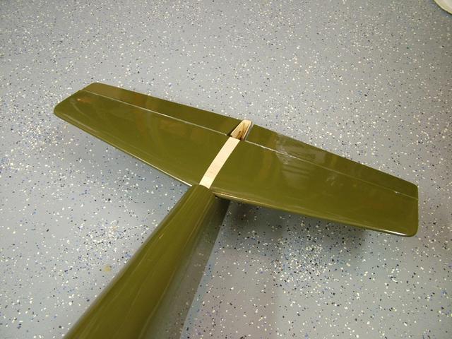
Attaching the tail assembly was the most difficult part of the build as there was nothing to help align the tail group to keep it straight. The first step was to epoxy the elevators to the joining wire and then hinge them to the horizontal stab in the same manor as the ailerons with CA hinges. Once done the assembly had to be marked where the covering would be removed. To do this the wings had to be mounted to the fuselage. Before marking the horizontal stab it has to be straight and parallel to the wing by taking a measurement from the wing tip to the elevator tip. Since the horizontal stab sits on an open cradle it constantly moved every time I tried to take a measurement. I finally was able to get it close enough and marked its location. I removed the covering and prepared it to be epoxied to the fuselage. Once the epoxy was applied to the cradle and the horizontal stab set in place, I laid a bean bag of lead shot on top to help hold the stab down while it dried. In the mean time I re-checked the measurements several times to make sure the stab was straight. This whole process told about an hour which I think was way too long. Like some of the other planes that have been review some sort of alignment feature would have been very helpful in speeding this process up.
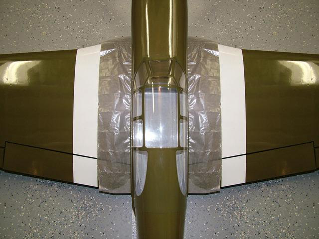
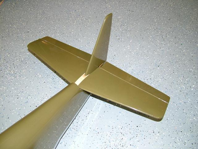
When the above assembly was dry the covering on the horizontal stab had to also be marked and removed before the vertical stab could be epoxied in place. The next part was one of the things liked least about this kit, a plastic fairing that slid over the vertical stab. This had to be glued to the fuselage, vertical & horizontal stabs. Again the covering was marked with a pen and removed so that a good bond could be achieved. Thin CA was used to wick between the plastic fairing and the wood surfaces. I personally feel pieces like this never really fit very well and just detract from the models overall appearance even a sport scale model like the P-51B. One important note is that this fairing needs to be added before the rudder is attached. The rudder is again attached with CA hinges as in the previous steps.
Hooking up the control horns and linkage were the next to do. Since the rudder servo had already been install all that needs to be done here is install the elevator servo, which is located in the tail of the fuselage. The servo sits in a small hatch much like the ailerons and flaps do in the wing. Securing the control horns and linkages was about as simple as it could be as the linkages were already cut to the proper length. |
|
| |
|
| |
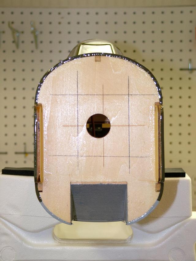
The kit recommends a Sato 100 engine to power the P-51B. The manual also includes a cylinder head, glow driver template for cutting out the cowl. There are no holes pre-drilled in the firewall for the engine mount, now this is one of those things that could go either way. Since the kit recommends the Sato 100 and describes the location for that engine mount for that engine in the manual it would have been nice if the holes were pre-drilled, but I understand not everyone will use the Sato 100 and different holes might be needed. Nonetheless I would have liked to see them pre-drilled. Following the detailed measurements given in the manual the hole locations were marked by drawing vertical and horizontal lines parallel to the thrust lines scribed in the firewall. The engine mount holes were drilled with a 1/4" bit and blind nuts inserted from inside the fuselage. A little CA was added around the blind nuts to keep them from backing out. The engine mounts are bolted to the firewall with 8-32 machine screws, make sure to use a little thread lock on each screw before tightening them down.
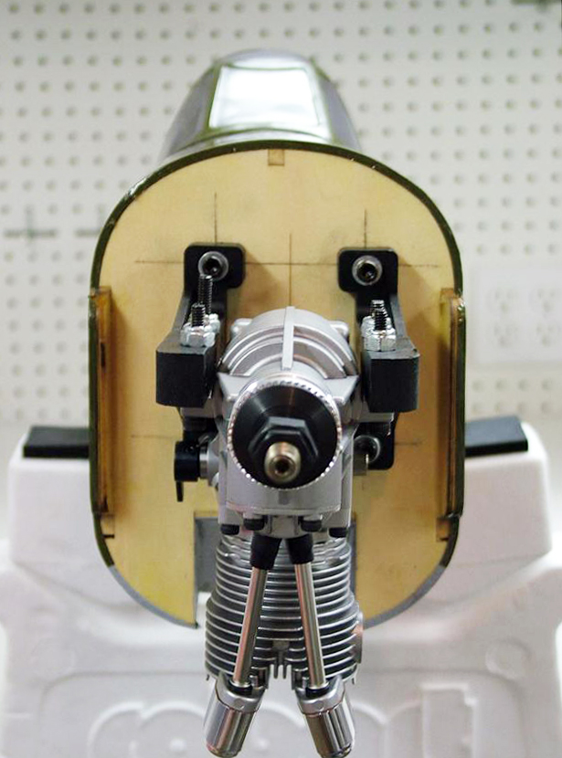
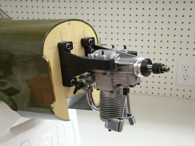
The engine thrust washer must be 5-3/4" from the firewall so that the spinner is in the correct location when the cowl is added later. Once in the correct position holes were drilled in the engine mount. The kit does not include the nuts and bolts for securing the engine so as you can see I did not have four bolts the same length but that shouldn't be a problem. It would have been nice to have included this as most engines is the size would use the same size bolts. With the Sato 100 mounted fully inverted very little of the head actually sticks out of the cowl which is nice for keeping the lines of the plane.
|
| |
|
|
| |
Although the cowl was the second item I like least about the kit it was more for the way it fit than the quality. The quality was very good and the color match was as close to the covering color as you could get. My only real dislike is how it fits to the fuselage, since it slides over the fuselage it does not fit flush it and has small gaps all the way around. However, installing the cowl is almost as easy as it could be, the templates made marking the head cutouts a snap. First, with the engine still mount I cut out the template and taped it to another piece of paper. I then laid the template over the engine heads and taped the paper to the fuselage. I removed the engine and having first marked the proper location of the cowl on the fuselage I slid the cowl on and used the template to mark where the cutout should be. I took the cowl off and used a Dremel tool to make the cutouts. I reinstalled the engine to check the fit and sure enough it was spot on. The manual instructs were to drill holes in the cowl to match up with wood blocks in the fuselage and again it was a perfect match. This is where the detail in the manual is really a plus and the engineering of the kit really stands out. The muffler and needle value cutouts were then cut in to the cowl to finish the installation. Instead of adding a fuel value as the manual describes I opted for a fill/drain line. So when assembling the tank I added a second clunk and have the line hanging out the cowl.
|
| |
|
|
| |
|
|
| |
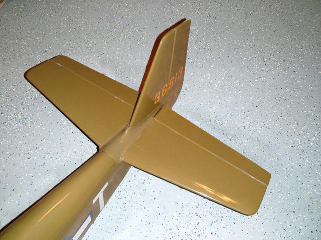
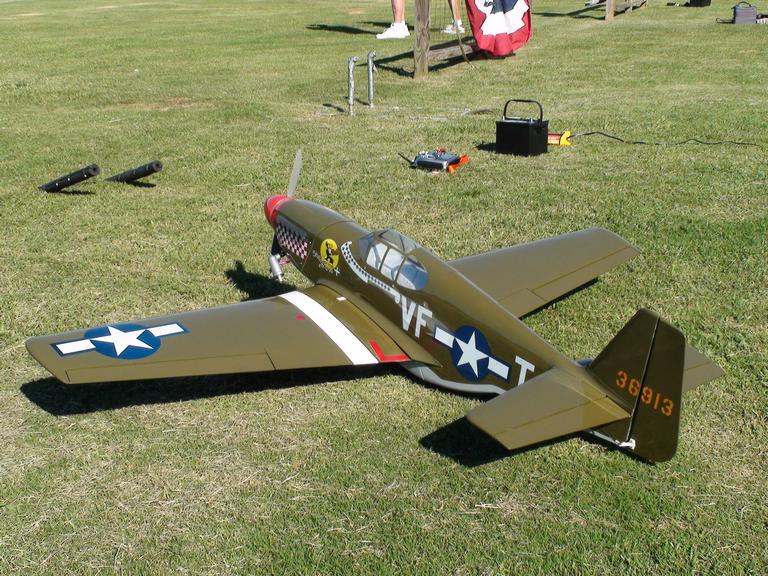
The last thing to do other than add the receiver and battery is to install the throttle servo and linkage. Again since I used the Sato 100 like described in the instructions the servo and linkage were a simple process. Aligning the linkage with the carburetor throttle arm I drilled the linkage exit in the firewall using a 1/4" drill bit. The linkage sleeve was glued in place and the linkage was connected to the carburetor and servo. That's about it; it was now time to apply the decals and make the plane look like the "Shangri-La"
The decal set that is included with the kit is adhesive backed vinyl and has to be cutout. The instructions also give details on how to apply the decals and is another reason why the manual is so long. The back cover provides a 3-view with where the decals go. It is really clear that a lot of time was spent creating the instruction manual and it shows the quality and attention to detail that is not seen in a lot of other ARF's. |
| |
|
| |
|
|
 |
| |
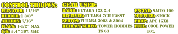
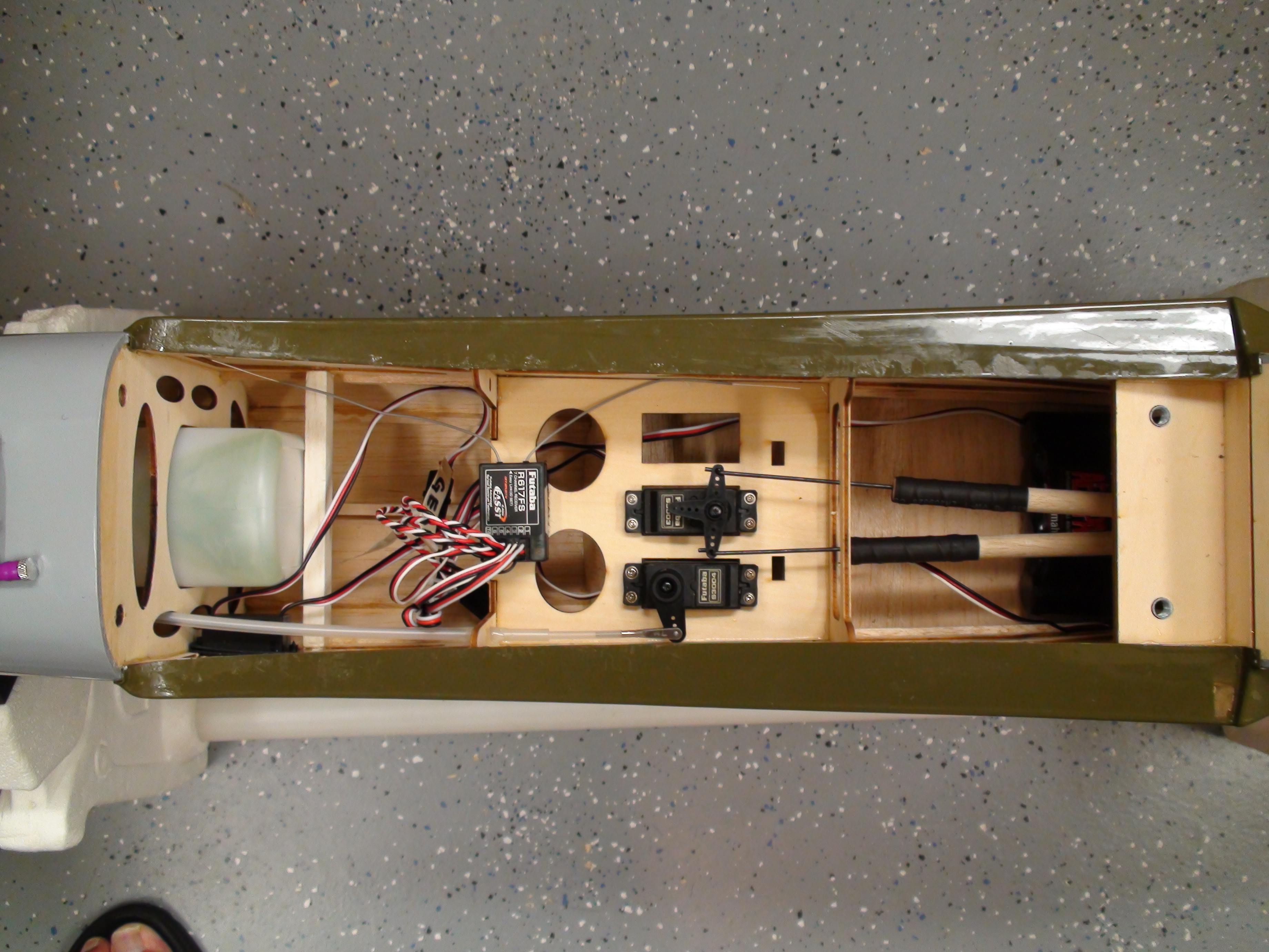
I used Futaba 3003 & 3004 servos with the exception of the elevator and retract servos which were a Hitech and Tower Hobby respectfully. The radio I used is a Futaba 12Z with the FASST 2.4 module and 7 channel FASST receiver. The nice thing about the 2.4 systems besides never having to worry about a frequency pin ever again is the fact that the receivers use very short antenna. No more antenna hanging outside the plane or strung up to the rudder. I used velcro to secure the receiver to the servo tray as it was the most convenient location. The Futaba FASST receivers do not suffer the same way FM/PCM receivers do from vibration, so it is not necessary to wrap it in foam.
The manual lists 7 different C/G points ranging from 27% of MAC (mean aerodynamic cord) to 33% of MAC. I used 30% of MAC which made the balance point 5.4" from the LE. With this balance point the plane was a little tail heavy so l located the JR 6V 2700mAh battery at the rear of the radio compartment. Doing this required no additional weight to get the plane to balance. Its important to note that the balance point is as close to the fuselage as you can get. The Mustang wing has a sharper taper near the root than does the rest of the wing. Using the measurements provided in the manual any where else on the wing will lead to an improperly balanced airplane.
The control throws were all adjusted to the recommended setting in the manual. Dual rates were also set for 60% of full throw. |
|
|
|
| |
|
| |
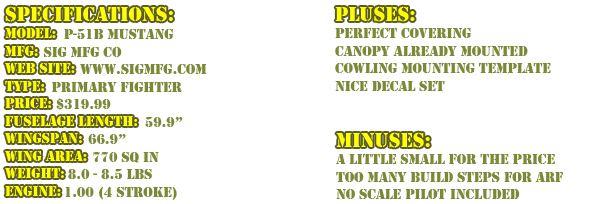
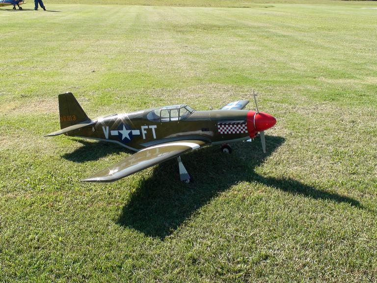
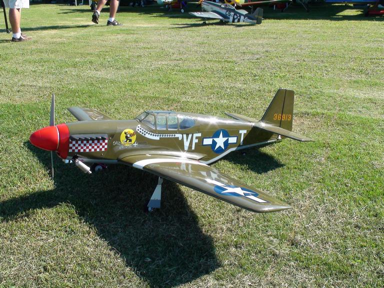
The P-51B and the BF-109 are a step above the other ARF's that Sig manufactures and it shows in the overall construction and covering. Compared to other ARF's the Sig MFG P-51B quality is better than most but for me required a little more effort to put together. At the price the plane was a little smaller than it competition and I would have liked to see more done at the factory. |
| |
|
|
| |
I broke in the Saito 100 with two tanks of Cool Power 10% fuel prior to going out to the flying field. The engine fired up with only a few turns of the prop and idled smoothly with no needle adjustments needed. The Saito 100 was a perfect match for the Sig P-51 as it had more than enough power to handle any and all maneuvers in the P-51's arsenal.
The test flight was conduct at the Georgia Model Aviators (GMA) flight facility. It was a beautiful sunny day with hardly a cloud in the sky. Although there was a slight cross wind it was a perfect day for the test flight. At the helm for the first flight was PJ Ash while I manned the camera.
The ground characteristic of the plane were excellent, taxiing true down the runway with only minor rudder inputs. With the flaps in the up position and at full throttle the P-51 took off with authority and in a very short span of runway. Once airborne the cross wind pushed the plane a bit but control was responsive. A few clicks of trim in the ailerons and elevator were needed to get the plane flying true. After a few passes were made PJ had planned to land but the performance of the plane and of the engine were doing so well that a few aerobatic maneuvers were performed. A victory roll and loop were both picture perfect and could easily been mistaken for the real thing. With a few maneuvers out of the way it was time to make a landing pass. Power was cut to just over 1/4 throttle and the flaps were deployed to about 1/2 provide a good sink rate that was slow and predictable. Making another pass, this time setting up for the final with the flaps fully deployed. Despite a near perfect approach landing was a bit bouncy. All in all however a very good first flight.
I couldn't wait to get my hands on the P-51, so once all the pictures were out of the way it was my turn. Despite being nowhere near the pilot that PJ is the P-51 was very easy to fly. I found it to have a very wide flight envelop being able to fly at very slow speeds with and without the flaps deployed as well as be able to tear up the sky at full throttle. Flying at half throttle is about all the P-51 needs for easy smooth flight. It can easily handle most scale maneuvers and looks good in the air. Overall the Sig P-51 gets high marks for it's fly ability and quality construction..
|
|
| |
|
| |
|
|
|
SIG Manufacturing Co., Inc.
P.O. Box 520
401-7 South Front Street
Montezuma, IA 50171-0520
www.sigmfg.com |
| |
|
|
|
Distributed Exclusively by:
Horizon Hobby, Inc.
4105 Fieldstone Road
Champaign, IL 61822
Main Phone: (217) 352-1913
Toll-Free: (800) 338-4639
Support Phone: (877) 504-0233
Sales Phone: (800) 338-4639
Fax: (217) 355-1552
www.horizonhobby.com
|
Distributed Exclusively by:
Great Planes
Model Manufacturing Company
P.O. Box 9021
Champaign, IL 61826-9021
www.greatplanes.com |
|
| |
|


-sm.jpg)
-sm.jpg)
-sm.jpg)
-sm.jpg)
-sm.jpg)
-sm.jpg)
-sm.jpg)
-sm.jpg)
-sm.jpg)
-sm.jpg)
-sm.jpg)
-sm.jpg)