|
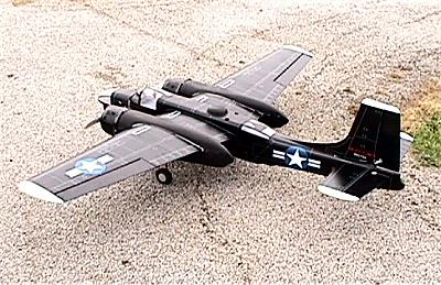
Model.............A-26 Invader
Airplane Type.......ARF Sport War Bird
Manufacturer........VQ Models
Suggested Retail Price.......$300.00
Anticipated Street Price.....$ 299.00
Wing Span.............Advertised....68.1 in.
Measured......68 in.
Wing Area.............Measured......777 sq. in.
Airfoil...............Semi-Symmetrical
Wing Structure........Balsa, ply, and hardwood leading and trailing
edges
Wing Joiner Method....9" plywood joiner
Fuselage Structure.....Balsa, hardwood, and plywood
Fuselage Length........Measured..54.5 in.
Pushrods Installed.....Outer Shells for twin elevator and rudder
Hinges Included........Yes
Hinges Installed.......Yes
Rec. Controls..........Ail,El,Rud,Throt ( Requires Minimum 6 Servos,
7 with retracts)
Engine Mount Installed..........No
Engine Mount Type...............Two Piece
Rec, Engines....................Two .25-.32 2 Cycle
Two .40-.52 4 Cycle
Fuel Tank Included..............Yes
Rec.Fuel Tank....................8 oz.
Landing Gear Installed...........No Fixed included...Provisions
for
Retracts
Wheels Included..................Yes
Rec. Wheels......................1.25"Nose, 2"-Main
Rec. Weight......................N/A
Assembly Instructions..........14 page picture book
Hardware: Metric or SAE.........Metric
Hardware Included...............Everything Required
Items Needed to Complete.....Propeller, two engines, radio, Six
servo extensions, two servo Y harnesses, two feet fuel line, Six Servos
(Seven with retracts), foam padding for two fuel tanks and radio, CA adhesive,
30 Minute epoxy, Assortment of 3/4" metal screws for the control
horns,4 of 1.25 " 2-56 Screws, Silicon sealant, and small 1/4"
long wood screws.
Covering Material.............Stick On Plastic Covering
Fuel Proofing Required........No, but recommended
Estimated Assembly Time....... 18-20 Std gear, 22-24 with retracts
Estimated Skill Required........Experienced
Drilling Required.............Engine Mounts, control horns, servo
mounts, (Additional with Retracts)
Assembly Tools Required.......Regular hand tools,drill bits, hobby
knife, moto-tool, allen wrenches, and scissors.
Completed Model
Finished Weight...................10lbs 4oz
Wing Loading.......................30.39 oz per sq ft
Engines Used..................... Magnum 52 four stroke
Propshafts to the Ground......7.5"
Fuel Tank Used...................As supplied
Radio Used.........................Futaba t6xa
Covering/Finishing used.......Pre-covered
Special Items.....................Added Spring Air Retracts, Hobbico
Multipurpose and Areo Gyroscopes, and MacDaniel on board twin glow driver
system.
Cheers- Parts fit very good and straight, installation of the rudder
sets dihedral of the elevator halves, mechanical push rod divider included
for the split elevators,' control surfaces preinstalled, heavy duty stick
on covering was straight and few wrinkles, aileron servos had premade
hatch covers, preparation for retracts already made, and what can I say....It
is a twin arf of a classic warbird.
Jeers.. Preglued elevators fell off in my hand during control horn
installation, additional wood trimming was required for proper fit of
the plastic covers, wing servo mounts were weak, wood attaching mounts
for the engine nacelles were weak and split, and the picture book instruction
manual is not for the novice builder. (Please see
update at top of page)
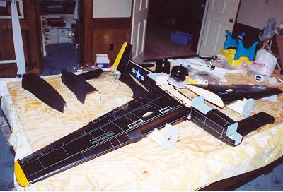
Building the Invader
As I am in the habit of flying only twins (See "Obsession in the
dictionary) it was a natural
me to get interested in the new A-26 ARF by VQ Models. The kit comes in
three colors, white, blue, and black. I chose the black one..Into the
night fighter stage!!
When I opened the box, I noted a complete kit in good shape and well packed.First
things first....Read the instructions before beginning the project. (
I thought I would try something new!!!! For those of us who do not like
or attempt to read the instructions first..I am here to tell you life
is good....There are no written instructions!!!! The whole manual is 90%
pictures and a minimum of written text. There is a legend for the obscure
picture symbols and little else.
Building the Wing
The precovered wing halves are fairly self evident from the pictures,
as to how they go together, using a single wing joiner of 1/8 ply with
around 4" overlap in the premade
boxes in each wing half. 30 minute epoxy is used to join the two halves
around the plywood joiner. The joiner sets the wing dihedral at exactly
the correct angle. The joint in as close to perfect, as far as being the
same size on each side, at the seam, as I have ever seen. I pondered the
wisdom of only one joiner, until I realized that the main flying stress,
on a twin, is carried on the wings..The engines!! There is relatively
little stress on the center joint as compared to a single engine plane.
On a single engine plane, the weight of the engine is transmitted into
the center of the wing at the fuse to wing joint. Not so on a twin with
the engines on the wings. The fuse is relatively light, and so puts little
stress on the wing joint. Further inspection showed that the leading edge
and trailing edge of the wing is spruce and not balsa, as is so many ARF's.
This further increased my confidence in the design. The firewalls were
already fuel proofed with some type of gray paint on both sides of the
plywood. I felt that better safe than sorry, so I sloped my usual generous
supply of 30 minute epoxy, just for good measure. Next the supplied engine
mounts were installed loosely to the engines, to get firewall to engine
nacelle clearance and spacing. I am using the Magnum 52 four strokes,
so the engines needed to be spaced as far back as possible. This is necessary
to keep the back plate of the spinner at the proper projection from the
engine nacelles. This rearward position really created a headache for
the throttle linkage. More on that later. The required hardware was packed
with the mounts. The supplied mounting hardware for the separate arms
of the engine mounts, is simply bolts and normal ' nuts and washers, of
which I loctited with "The blue stuff". One point to be aware
of, is the width of the four stroke engines mounted upside down, made
the spacing of the mounts so wide that I had to grind a bit of the triangle
stock from the back side of the fire wall to get the nuts, washers, and
lockwashers on. Probably not a problem with upright two stroke engines.
The fuel tanks are mounted at this time. The tanks are not marked as to
size, but I would venture a guess of 6 ounces. The outlet construction
is the normal two ports for inlet and outlet. There is a third outlet
at the top of the tank for a vent to the muffler and was already open.
Normally, I use the
curved tube inside the tank for this,but saw no harm in using the supplied
molded vent. You will note that the tank is impossible to mount upside
down, due to this vent outlet going through the firewall. Here you do
not want to mount the tank tubes as pictured or you will have no muffler
pressure. It shows in the series of pictures that the extra tube from
the tank is for filling. You cannot reach it unless you let it hang out
and plug it after filling. The kit does not include a large sheet of 1/4"
foam that must be cut to form a seal at the tank neck through the firewall,
as well as supply a cushion around the tank. Here would be a good place
to note that building tip in some type of written instructions. The pictures
show mounting the tail cone of the engine nacelles at this time. I would
suggest not to mount it until the engine controls are finally installed
and adjusted, to prevent damage.
The engine nacelles are fit up and cutouts made for the engine. Note the
picture on the box for the "Bump" of the engine supercharger to be properly place up. I
would point out that these nacelles are some type of PVC as in most kits, but these are already reinforced
with fiberglass mat. I'm impressed! Impressed until I started grinding
them for the engine head projections and the dust flew everywhere (Wife
did not catch me until I was out of the house!) The rails for the throttle
servo and landing gear mounts are already in the engine nacelles. If you
opt not to use the hard wood mounts and go with air retracts, the mounting
rails are already installed. In fact the supplied fixed gear must be mounted
into adapter blocks (Supplied) for the main and nose gear. If you are
using retractable landing gear or fixed, cut out the openings in the bottom
of the nacelle cover before installation. (Not covered in the picture
instructions.) The pictures show that the covers are to be screwed in,
with the supplied screws, and secured with C.A. I chose to use Plumbers
"GOOP" as I might some day want or need to service the landing
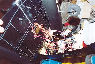
gear. You could also use silicon sealant. The passages for the wiring
for the aileron and throttle servos were prerouted with string for easy
installation of the wires. You need two "Y" cords for the ailerons
and throttles for standard installation.
Mounting the Tail Feathers
Take the inserted areas of the elevator halves and the bottom of the rudder.
Cut off approximately 3/16" of the covering, to make a good glue joint.The elevator halves
are slide into each side of the
fuselage and the rudder slide into the top. When the elevator is in place
the dihedral of the elevator halves is set...sort of. Make sure the fuse
is held down and level before beginning this procedure. After inserting
the rudder, and before the epoxy sets, measure that the elevator halves
are equal height from the table so that each surface is at the same angle,
and that the rudder tip is the same distance from the elevator tips.
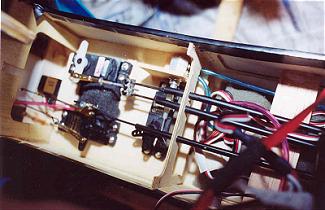
Control Mounting
The control horns are mounted next. The good news if that there is no
problem to find the correct hardware to mount the control horns..The required
screws are right in the package with the horns. The bad news .Not one
of the machine screws is long enough to reach through the elevator or
rudder, and forget about the length required for the built up ailerons...Almost
1.5 inches. Substituting 6-52 screw and all thread worked fine.....Until
one of the premounted elevator halves fell off in my
hand...Not a confidence builder!! The other control surfaces seemed strong
enough, but I used small wood screws and epoxy on all of the hinged area
to be sure. I painted them black to not be obtrusive. When mounting the
aileron servos, I again had one of the preinstalled rails for the aileron
servo come off. I pulled the other servo mounting rails off of the servo
covers and re-epoxied them all and added triangle stock to be sure. If
you plan to use pneumatic retract mechanism, now is the time to install
the air tank under the push rods for the rudder and elevator. There is
already a circular cut out for the tank in the fuselage. Be sure to install
the airline to the tank, as it is difficult to access with the reach rods
in place. The supplied push rods seemed a little light for my taste for
the elevator and rudder control on a powerful twin engine plane. I substituted
4-40 rods inside of the preinstalled outer covering for the push pull
push rods. This is my personal feeling, the supplied rods may have
been fine, but for me better to change if any question on a fast plane.
The mechanical joiner for the two elevator halves is supplied, and I drilled
out to accommodate my 4-40 rods. I maintained the 2-56 for the connection
to the high torque elevator servo. The rudder connection I also used a
4-40 rod to a standard servo. Even the connectors for the reach rods,
at the servo arms, was furnished and of good quality.
Engine Control Installation
As I chose to install Magnum 52 four stokes inverted, the engines must
be mounted as far back as
possible to get realistic prop clearance. This poses a real problem with
the reach rod installation. There is no room to install a normal clevis
due to the closeness of the firewall. Simply installing a loop from above
to the reach rod was not normal, as the loop hit the cylinder head and
to make is short enough to follow the arc of the control arm on the carb
caused binding from closed to open. My solution was to run a metal push
rod ( Furnished in the Kit) from the servo (which is not accessible after
the nacelle covers are installed) formed into a 3/8" loop, to a slip
type connector on the throttle control arm on the carb so that small adjustments
for equal engine operation was possible. I put the plastic push pull rod,
that I previously rejected over the rod, and ran the whole mess though
an outside covering for the plastic rod and through the fire wall. The
covering was run 6" inches into the nacelle to prevent fuel from
coming into the nacelle. This loose fit at the fire wall allowed the rod
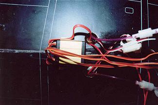
to move up and down without binding. I also installed the McDaniels on
board glow drivers, for twin glow plugs, for the inverted four stroke
engines, for safe starting and increased reliability.
Canopy Installation
The instructions say to install the various canopies at this time. I waited
until the retract system was installed. This to prevent damage to the
clear canopies. The instructions again indicate, to mount with CA. I used
"Goop"
Retract Installation
I used the Spring Air System for this project. Note, these are not supplied
with the kit. The structure is already set up for pneumatic retract systems.
As previously stated, the kit contains the adapter blocks and pictures,
to install the included rigid mounts, but the under covers and frame work
is already done for retracts.The retract manufacture's instructions should
be followed for connection, but there is a pretty self evident set of
pictures in the instructions as to how to mount and plumb the air system
and install the retracts. They leave out how to connect the steering gear
to the rudder servo.
Control Throws
Learn to fly with the rudder or leave twins alone!!!! I set the recommended
throws at 1/2" for the ailerons and elevator. I did not agree with
only 3/4" rudder throw, to keep me out of trouble in the event of
engine failure, I want all of the rudder control I can get. I set it to
1" each way, which is all that is possible due to rudder interference
with elevator.
Gyro Installation
While not necessary, I am into insurance wherever possible. I chose to
install two gyros in this plane to make sure of sufficient time to react
in the event of engine failure. I installed the Hobbico Multipurpose gyro
on the rudder and set for 50 % gain. The Hobbico Areo Gyro was installed
on the ailerons and connected to a separate channel's rotary dial, on
the transmitter, for gain control from the ground. Starting point was
50 % gain. If the plane's wings start "bouncing" up and down,
the gain, for the aileron's gyro, can be reduced as needed. If an engine
fails, the plane's reaction is a quick yaw into a snap roll. The slower
the airspeed and higher the power, the faster the snap roll will occur.
The gyros dampen the action enough to be controllable and save not only
your nerves, but the plane as well. Additionally, the manuvers are very
crisp and landing is a breese.
Wing Installation
Slide the wing onto the fuselage, and secure with the two supplied nylon
bolts. The plastic cover over the wing and on the fuselage cut out for
the wing, has cut outs for the wing hold down
bolts. They are accessed by removing the plastic covering over the precut
holes. Once the prefabricated cover, over the wing, is installed, the
wing bolts get a bit difficult to access as they are inside of the cover
by one inch. A tube for access would have helped at this point.
Now install the various canopies, plastic nacelles, and decals that come
with the kit!!! The plastic
nacelle covers that come with the kit are secured via wood screws into
the wing sheeting. I found that the plywood formers needed to be trimmed
down so that the plastic covers,behind the engines, would fit flush with
the wing surfaces. If you want to add a little additional scale "Guns",
they can be
fabricated out of 1/8" dowel rods painted black and glued in place.
You can either paint the "glass" nose windows black, or make
out of balsa. I found that the batteries had to be put into the nose for
proper balance. This requires a long drill to get through the front landing
gear bay.
TIME TO GO FLY!!!!!!
A Few Twin Flying Tips
Twins are no more difficult to fly than single engine planes. They typically
feel "Heavier" due to higher wing loading, but control is similar.
I do not subscribe to the widely held view that the remaining engine,
on a twin, gets you to the crash site sooner. It is just not true!
Rule number one. Always have a copilot to handle a twin. There
is a lot of flying propellers and less places to safely handle a twin.
Rule number two. Always start the engine farthest away from you
and get it set, before starting
the engine nearest you. You do not want to be reaching across a running
engine to start or adjust
another engine.
Rule number three. Reliability is the single most important aspect
of flying a twin. Set the engines
a little rich. Match the strong engine to the weaker engine..Never the
other way around. Always ALWAYS!!! Bring the engines to full power and
hold the plane straight up for 6-8 seconds. Any sign of a sagging engine
means trouble. Correct it now and do not take off until the engines pass
this test without a significant loss of RPM. Loss of an engine, on take
off, is death to a twin!! A fast snap roll, and it is over.
Rule number four. If you lose an engine, gyro or no gyro, the plane
will begin to yaw, and raise the wing on the good engine. Throttle back...NOW!
Lower the nose, to keep airspeed, and so control up, and make immediate
plans to land. You can fly on one engine as long as the airspeed is up
and the air is going over the control surfaces, but a snap roll is just
a heart beat away, if the remaining engine is much over 60% power. Turning
away from the running engine is inviting a snap roll. Throttle back, and
turn toward the good engine. Once the new course is established, slowly
bring the throttle back up to a maximum of 50% power. Here less is better!
The idea is not to continue to fly, but to get into a safe landing position.
Once on final approach, chop the throttle and land. Never bring up the
throttle on the remaining engine on final approach. The plane will roll
over into the ground quickly.
Rule number five. If you don't currently know what the left hand
is for, the rudder, it is extremely
difficult to handle a twin with an engine out. The rudder is very important
to control a plane that
is trying to yaw away from the running engine. The ailerons alone cannot
handle single engine operation. Learn to fly using the rudder!!
The above discussion is intended for beginner twin pilots. I realize that
multi-engine planes can be
flown with one engine and loops and rolls are possible. I have even taken
off with one engine, but this is not for the beginner, and should not
be attempted until much time is spent in the company of multi- engine
planes,and their control.
Flying the A-26
The final part of any model is flight. The day arrived to actually fly
the plane. Note, the actual plane used for the flight was powered with
two Thunder Tiger .36 engines using APC 9x6 two blade
props. Two type of flight tests were performed. One with the gyros and
one without. The engines were properly broken in, brought to full power
using powermaster 15% fuel. The plane was held straight up by my co-pilot
and engine stability checked. Minor readjustment was necessary at this
point to assure engine stability and reliability.
The plane accelerates like a rocket. The rudder is very responsive to
input on take off. A little exponential would be good at this point on
the rudder. If the gyro is used, rudder control on take off is almost
a non-issue, as long as the engines come up together. At take off speed
the plane lifted right off and only required two clicks on the elevator
for landing gear changes, and one on the ailerons.
In Flight
The plane will fly very well at approximately one half throttle. Loops
were large and stable, with or without the gyros. The plane has no flaps,
and does not need them. A nose high approach is very controllable and
smooth. If the gyros are used, the landing is engines and elevator. The
wing loading is heavier than pattern ships and trainers and so landing
and pattern manuvers are at higher speeds.
Rolls are smooth. The twin gyros on will really make four point rolls
crisp. Ok Ok so it is not a
patterm ship, but we need a little fun. The plane flys with up trim needed
on the elevator until the gear is retracted. At that point, the elevator
trim is almost neutral. A computer radio is helpful at this point to program
a mix to change the elevator trim for up and down landing gear.
Single engine operation
Naturally, during the testing one engine died....Ok so I violated rule
number one of always doing
the vertical test and the temperature changed. With the gyros off, the
plane tried to yaw into the dead engine. Rudder and ailerons were added
to correct. The remaining engine was brought to approx 15% power and a
turn into the running engine was performed.The power was brought back
up to approx. 75% after the turn, and the nose pointed down for the landing.
No attempt was made to fly the model on one engine, due to deadline on
this story and lack of guts on as yet unfamiliar model. From past experience,
the gyros would have made the engine out easier to handle at the surprise
outage, but the plane flew well on one. Note, the pilot is an experienced
twin flyer. Single engine operation, on any twin, is not recommended.
Summery
All in all a very good flying model with no notable bad flight characteristics.
Looks fantastic in the air and on the ground. The rudder is very responsive
and needs to be for a twin. One problem is with the covering. In direct
sunlight, it begins to wrinkle quickly. For the most part it goes away
as it cools. This covering will not lend itself to repairs. The nose art
on this model was provided by the owner of the model who actually flew
the A-26 in Korea.
|