|
| |
First Impressions:
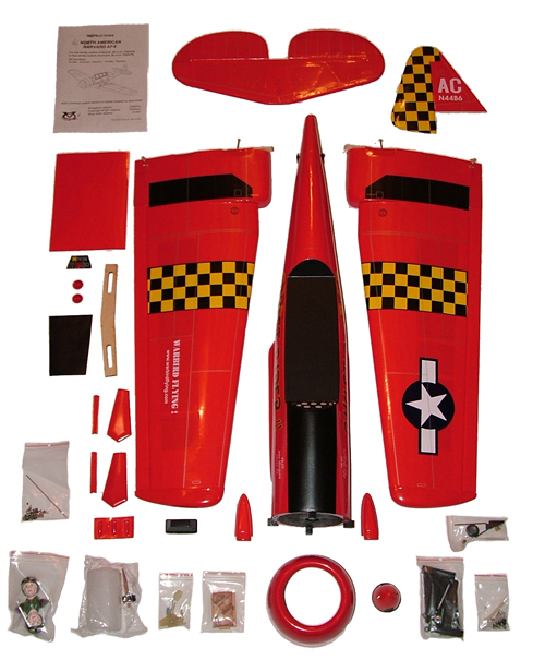
Upon receiving our review plane it was very nicely packaged to prevent any damage during shipment. Everything was neatly and individually packaged in plastic wrap or zip lock bags.
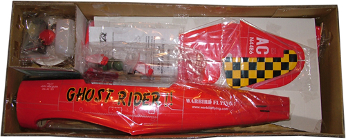
The VQ AT-6 ARF retails for $169.95 and for the quality of construction and included hardware is a very nice price. The kit includes all the hardware, except fuel lines, that was needed to assemble the plane. It even includes mechanical retracts. The first thing I noticed was the quality of the hardware, and in my opinion it is a step above what you find in most ARF's. As an example the hinges are plastic pin style not CA style. Another nice feature is the plastic film covering; I'm not a big fan of Monokote film because I find that it wrinkles too much or does not stick very well. Adhesive plastic covering is not new to ARF's but I particularly like it over Monokote. So I found the adhesive backing plastic film to be a nice touch. It was wrinkle free out of the box and comes pre-printed with all the graphics including panel lines and rivets already in place. The only thing that I felt a little concerned about were the ailerons. They run the length of each wing and are very narrow, so my first thought was that the roll rate will be a little slow. The flight test may reveal something totally different so I will wait and see. |
|
Items Needed to Make Flight Ready:
- Radio System (Minimum 5 channel)
- .46 - 2 Stroke Engine or .52 - 4 Stroke Engine
- Propeller
- Silicone fuel tubing
- 4 - Standard Servos
- 1 - Retract Servo (180°)
- 1 - Servo Extension (6")
|
Construction:
In reviewing the instruction manual two things immediately jumped out at me! First this was going to be a very fast build and second several of the steps in the manual had already been done for you by the factory. The mechanical retracts were already installed and the ailerons were pre-assembled to the wings. So without doing anything Step 1 is already done. In
Step 2 the manual indicates a need to attach the wheels but this was also done at the factory so all I needed to do was attach retract door covers with the supplied 2x6mm screws. In Step 3 the two wing halves were joined together using 30 minute epoxy. For this I mixed equal parts of epoxy and microballons, the microballons will help provide a stronger bond between the glued sections. |
| |
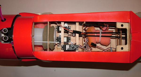
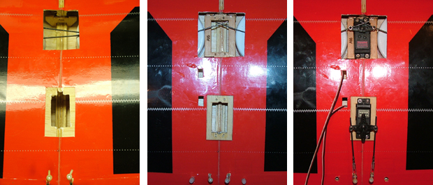
Once the epoxy was fully cured it was time to install the servo trays for the aileron and retract servos. In step 4 the aileron servo tray gets glued to the wing sheeting so this step required laying the servo tray on top of the covering film and marking its location. The covering was then removed to expose the balsa sheeting and the servo tray was glued with CA. The retract servo tray took a little more work to get installed. I needed to enlarge the wing opening where the retract servo was to be mounted. Once I had a little more room to work with, I used CA to glue the servo tray uprights in place against the wing ribs and then glued the servo tray to the uprights.
Step 5 the servos and the control linkages were installed. Here is another example of what I consider nicer hardware. The servo arms get metal linkage keepers that are screwed together instead of the standard nylon snap-on type. The most time consuming part of this step was connecting the retract linkage rods which had already been installed at the factory. The rods needed to be cut to length and attached opposite each other on the servo arm so that when actuated the maximum amount of travel is achieved. Most of the time was spent fine tuning the gear to get it to cycle correctly. When the servo operated smoothly I had a little more play in the gear than made me feel comfortable. Taking the play out of the gear caused the linkage to bind. Before the first flight this will need to be worked on some more.
UPDATE: As mentioned above I originally had some difficulty getting the gear to cycle smoothly. After careful study of the problem I realized the I should have looked at the instructions more closely. I started with the largest servo arm I had, thinking that I needed the most possible travel. Actually all that is needed is the stardard small round servo wheel to get the gear to work perfectly. Once I changed out the servo wheel all worked as smoothly as designed.
|
| |
 |
| |
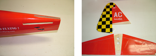
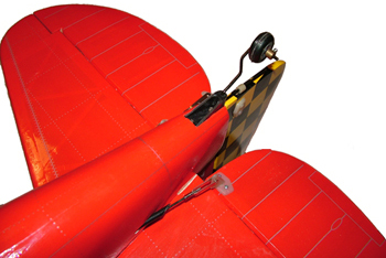
Step 6 the vertical and horizontal stabilizers were joined to the fuselage. The excess covering on the fuselage needed to be removed first before dry fitting the control surfaces.The horizontal stab was first dry fit and checked for straightness by measuring from the firewall centerline back to each stab tip. The measurement should be equal on both sides. Once straight the horizontal stab was marked with a felt tip pen to indicate the fuse location on both top and bottom. The vertical stab was also dry fit and marked. The stabs were then removed and the covering is cut to the inside of each line to expose the balsa below. Once this was done the horizontal and vertical stabs were epoxied to the fuselage. Again I mixed equal parts of 30 minute epoxy and microballons for a stronger bond. The rudder also needed to have the lower hinge epoxied at this point. Once dry the elevators were also epoxied to the horizontal stab. Since these are not the standard CA style hinges they needed to be epoxied. A little Vaseline was dabbed on the each of the hinge joints to keep the epoxy from gluing the hinge.
|
| |
|
Step 7 the tail wheel assembly was mounted. Some covering needed to be removed to expose the tail wheel pocket in the fuse as well as in the rudder. The tail wheel bracket was screwed in place with two 3Mx12mm wood screws and the tail wheel was attached with a collet. A small rudder keeper slides on to the tail wheel wire and was glued to the rudder using CA. |
|
| |
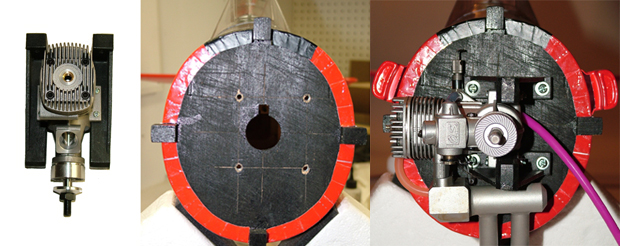
Step 8 the engine was mounted and the throttle linkage was installed. Here the engine, an OS 46FX, was first attached to the included engine mounts to set the proper spacing. It was then placed up against the firewall to mark the engine mounting holes. The firewall was marked with centerlines to help center the engine mount. Four 5mm holes were then drilled into the firewall and blind nuts were secured from inside the fuselage. A little CA was used to help keep the nuts from backing out. The engine with mount was then bolted to the firewall with four 4Mx25mm machine screws. A dab of thread lock was applied to all of the bolts that secure the engine to the mount and the mount to the firewall. The throttle linkage hole was marked on the firewall and a 3mm hole was drilled. The standard muffler which came with the OS FX46 engine interfered with the fuselage and would have required substantial modification to the fuselage, so a Slimline Pitts style muffler was used instead. However this muffler interfered with the engine mount so a custom made extension was made. This was done by cutting off a section of the standard muffler and filing down the cut face. |
| |
|
| |
Step 9 the fuel tank was assembled and mounted in the fuselage. As mentioned the silicone tubing is not supplied with the tank and needs to be provided by the builder. Once assembled, the tank was mounted in the fuse in a cutout designed to hold the tank. A few small pieces of foam were placed between the tank and the fuse rib to keep the tank secure.
Step 10 the engine cowl was installed.
Steps 11 & 12 the servos were installed in the fuse and the control linkages connected. In this step I had to make some modifications to fit the servos and linkages. First I inserted the linkage rods into the linkage tubes already installed in the fuselage to line up the control horns. I secured the control horns to each elevator and to the rudder. The rudder servo was installed first and the metal linkage keepers attached to the servo arm. Here the rudder control rod did not line up with the servo arm so I drilled a new hole in the bulkhead to move the control rod over. The elevator linkage rods were cut to size and connected together using a connecting block. The elevator servo was then installed so that it lined up with the linkage.
Next was the most difficult part of the assembly and required the some modification. The throttle linkage supplied is a rod as opposed to a cable so therefore it was limited to how much it could bend. The position of the throttle on the OS 46FX forced the throttle linkage to enter the servo compartment well above the servo tray. In order to keep the binding to a minimum the throttle servo had to be moved above the other servos. |
| |
|
| |
Steps 13 & 14 the pilots and scoops along with the canopy were installed. Another nice feature of this kit is that it comes with two pre-painted pilots. They were glued to the cockpit deck with CA along with the backseat instrument panel. The IP has a sticker that gets applied before it is glued. The kit also comes with two vacuumed formed scoops that I glued using CA. The canopy first needed to be trimmed and secured with eight small wood screws. The canopy comes unpainted but a there is a sticker sheet that strips can be cut from to apply to the canopy frame areas. |
|
| |
Step 15 was to attach the wing to the fuselage. The wing has a tab that sticks out forward of the leading edge at the center and is inserted in to a notch in the fuselage to secure the LE. The trailing edge is secured with two 6Mx38mm nylon bolts. The mounting holes in the wing are pre-drilled at the factory so all that was needed to do was to cut a hole in the covering to expose them. The fuselage also has the blind nuts already installed so there is not much to do in this step. |
| |
Step 16 & 17 are for installing fixed gear and are therefore skipped since the kit came pre-installed with mechanical retracts. |
| |
| Step 18 & 19 document the control surface travel and the CG location. I used the 3-3/8" position as my balance point. |
| |
| Control Throws |
Gear Used |
Elevator: ± 7/16"
Rudder: ± 1 - 1/4"
Ailerons: ± 1/4"
C/G: 3 - 3/8" to 4" |
Radio: Futaba 12Z
Receiver: Futaba R149DP
Servos: Futaba 3003 & 3004
Retract Servo: Futaba FP-S136G
|
Engine: OS FX 46
Muffler: Slimline Pitts
Prop: Master Airscrew
Fuel: |
| |
That's it, the plane is now ready for it's first flight. All in all a pretty easy build and not bad looking for a sport scale plane. Stay tuned for the flight report. Click here for the Flight Report. |
| |
|