By Sam Parfitt
Page 2
 |
This is the box of 28 or so servos ready for my P-61 (never
have too many servos).
I'm using Hitec HS475HB. They're 76 oz torque for 6 volts. More than
enough for flying this plane and when at least 13 servos are needed,
at 18 bucks apiece,
saves a lot of money over more expensive servos (I'm using a JR 8103).
For the low profiles needed for the spoiler/aileron combo, I'm using
Hitec HS-77 (also 76 oz at 6 volts).
|
|
I'm starting with the outer wings instead of the center wing that
the manual starts with, because it has the spoiler and I had to see
how that works first.
The servo cover farthest away from the wing tip is for the outer
wing flap. I mark each cover as I take it off with an arrow showing
which part is pointing to the front and also its purpose. (Screws are
already holding the covers on: another nice touch).
The servo mounts are already glued in. Looks like they did that because
they are at an oblique angle to the cover and they didn't want us to
hose it up. |
 |
 |
As you can see, the servo fits the mount perfectly. The
mount seems very secure but I'm going to put some epoxy on the mount
anyway (just to make sure!).
I use a Dremel tool to drill the holes for mounting the servo,
I temporarily put a thin piece of the servo box flap between the servo
and cover while drilling the holes. This keeps any contact with the
plane so less vibration is transmitted to the servo and possible feedback
to the receiver.
|
The pin hinges are glued into the flap and glued into
a block of balsa that slides into a square hole in the wing.
Never seen this before but very ingenious.
|
 |
 |
The center cover is for the combo spoiler/aileron servo.
This mounts in the wing and not on the cover. Here I'm using HS-77 (ordered
two of them and should be arriving in a few days).
Another nice touch: spoiler and aileron from one servo. Watch when drilling
the holes that you don't go through the top of the wing. The only safe
way from keeping from doing this is to put a small piece of metal between
the mount and top of the wing.
|
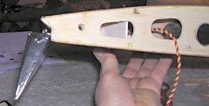
Here's a picture of the spoiler in the up position (cool
stuff). |
 |
 |
Next is gluing the flap to the wing.
This is how I did it to insure that all is aligned and moves freely(you
don't want to glue these incorrectly).
I used masking tape to tape the flap so it is aligned with the top of
the wing.
I like to stick the tape to my leg first to reduce it's adhesive qualities.
Use good 3-M tape and not stuff that's been in the garage all summer.
|
This side view shows a nice smooth transition from the
wing to the flap.
There should be a very fine line between the top of the back of the wing
and the top of the flap.
The profile picture shows that VQ did their homework: the back of the
wing isn't flat like on most ARF wings.
|
 |
 |
Now that the top is aligned, put straight pins into those blocks
of balsa from the bottom of the wing to temporarily hold those hinges
at the correct location. Now remove the tape and insure there is free
movement down for the flaps.
|
|
Pins in the bottom of the wing |
 |
 |
Tape removed.
If all moves freely, you can tape the flap back up and wick thin CA
between the balsa blocks and wing. This should insure you have no
turbulence from large cracks between the wing and flap nor any binding.
NOTE: I tried to move the spoiler up but it wouldn't work. Found out that I must have put too much CA on the flap hinge and it
glued the spoiler to the wing.
Easy fix: a razor blade cut it loose (only about 1/4" long).
Put a piece of wax paper between the spoiler and wing or put it in
the up position when CA'ing the flap hinges.
|
So far, I'm impressed with the design work of this ARF:
Some people may think the price is high but all those fine details added thus far makes this a cheap plane.
(HMMMM, for me to design and build spoilers: that will take me about 20,000
hours, not counting calling on higher powers to stricken it down!) |
|
We're going to need 2 'Y' connectors for the flaps since we have
3 servos to connect. I just double checked the outer wing servos: also
need a reverser for those. Might as buy 2 or 3: we may need them with
coordinating 2 rudders & nose wheel and the horizontal stab has
2 servos.
Also, noticed that it is going to be difficult to adjust the connecting
rod from the servo to the flap on the outer wings. The servo is mounted on the cover and I don't think that plastic ball
joint is adjustable. An easy way would be use two channels: your call.
(we may need a 12 channel by the time we're done: especially if we make
the pilot wave!). |
 |
 |
This is the top view of the center wing with the flap servo
mounted(it faces to the rear-just as the outer wing flap servos do).
There is a rectangular hole in the top and bottom of the wing where
the covering has to be removed. The manual doesn't mention the hole in the bottom but the covering has
to be cut away so the bottom of the standard servo can fit in the mounting. The two covers removed on each side of the center servo has two 90 degree
control horns already mounted with easy connects. One end of the 90 degree control horns will go to the center servo and
the other side will go to the flaps.
|
I noticed about a 1/32 to 1/16" play between the
hinge balsa blocks and the holes in the wing. I put some slivers of balsa in them to make a tighter fit and for better
adhesion for the CA. As we did with the flaps on the outer wing, follow the same procedure
for the center wing using tape and pins.
All my hinges connecting to the flaps were already glued in but it doesn't
hurt to check yours: with 65 planes built times
how many hinges? Esc: there's bound to be one or two missed.
Same goes for the ailerons: mine are already glued in but there could
be some missed by the 'gluers'.
Also, check that ball socket on each flap: a little CA on the nut won't
hurt (easier now than when the planes flying!).
Here's a 'DUH' statement but just in case someone doesn't know:
The brass grommets that go through the rubber mounts on the servos,
the rounded end contacts the wood mount
while the sharp end is for the screw head to contact. Reversing it can
cause the sharp end to cut into the mount when the
screw is tightened (servos moving in their mounts while plane is flying
is not good). |
Bottom of the center wing with the servo sticking out. |
 |
 |
I mounted the center wing to the fuse to make sure the servo doesn't
hit anything. All looks good. A nice tight fit exists between the fuse and wing.
|
I worked on hooking up the flap servo to the flap (makes
sense!) on the outer wing. I had to replace the rod that comes with the
ARF: very brittle and broke on a 90 degree bend. Another one did the same.
I recall the P-38 had the same problem. I had to put a small S curve in
the wire to keep from binding and to align the servo arm to the flap socket.
I'm holding the cover outside the wing so you can see the alignment.
This picture is the up position. |
 |
 |
This shows the relative position of down. The rod moves about 1/2".
|
Having the cover turned upside down, you can see the
bends that I needed.
The rod is 3 15/16" long from servo arm bend to center of socket.
Of course there's a lot of variables from my setup to yours but it gives
you a ballpark area. |
 |
 |
Flap up. |
 |
Flap down.
If that should be enough down!
|
I'm working on the rest of the flaps in these pictures.
I had to enlarge the hole where the brass socket moves on the flaps.
Even if you miss doing it before gluing them on, there's plenty of room
to enlarge the hole after installing them.
|
 |
|

Flaps up. |
Inner wing flaps:
I couldn't find any rod in the ARF that seemed hefty enough to connect
the servo to the two 90 degree horns so I pulled one out of my 'stock
pile'. This goes together surprisingly quickly. One servo in the middle connected to the two 90 degree control horns. Connect the 6" long rods with the sockets to the flaps, adjust
and all done.
|
 |
Flaps down. That should be sufficient!! |
I see why Twinman says the P-61 flies so much better
than the P-38! |
 |
|
|
I couldn't wait and jumped to the last step of building. I dry fitted
everything together to see what it looks like: GREAT , WHAT ELSE!
The center wing, two booms and horizontal stab go together just like
the P-38 did: perfect fit on all parts. I left 1/8" of covering where the horizontal stab is jointed to
the booms and just pushed the stab into the recess.
I figured this would keep any covering from coming off in the future.
Put the horizontal stab between the booms before connecting the second
boom: Once the two booms are attached to the center wing, there's no
slop in there to be widening the tail of the booms
for the stab.
Booms and center wing and fuse are all connected with nylon screws.
The horizontal stab is connected with metal screws. The stab is symmetrical
with duplicate patterns on both sides and can be put on either side
up.
What a GREAT LOOKING PLANE. |
|
Notice: Questions
or statements regarding product quality and/or usage are solely the
opinion of the writer and not necessarily the opinion or recommendation
of rcwarbirds.com or rcwarbirds.com owner/webmaster. By asking a question
you are giving rcwarbirds.com or rcwarbirds.com owner/webmaster the
right to post your question and name on this page. Not all questions
are answered or posted. All questions and answers are copyright rcwarbirds.com
|
BACK to REVIEWS
|
|
Become an RCWarbrids site supporter by making a donation.
|
$5.00 |
 |
$10.00 |
|
$15.00 |
|
$20.00 |
|
| |
|
|
|
|

