|
By Sam Parfitt
Page 5
 |
First, I had to fill in the hole in the firewall with some
balsa and epoxy.
This is a good time to make sure none of those engine mount bolts are
sticking out the back (very hard on fuel tanks: I learned the hard way!).
I had one sticking out on each boom since I had to narrow the mount a
skoch to allow for muffler room.
|
I drilled and tapped holes for the pressure to the fuel
tanks. A couple 6X32 aluminum bolts does the trick.
I find ACE and other small hardware stores has an excellent selection of
small screws that HD and Lowes doesn't have. |
 |
 |
I had to drill a 1/16" hole through the aluminum screw.
I cut the heads off first. I then use two nuts and tighten them against
each other to keep the bolt from spinning (also to hold the bolt in the
vice). Center punching the screw and using a good quality bit are essential,
plus exact perpendicular to the drill table (there's not a whole lot of
slop allowed when drilling a 1/16" hole through a bolt that's only
about an 1/8" diameter. The aluminum bolts are cheap though so no
big deal if you break through the side. I drill half way through from
both sides to reduce this risk and I use cutting oil to keep friction
down (especially essential when drilling steel to prolong the life of
those bits). Even if you break through a small amount, a little JB weld
will fix her up (just make sure you don't block the vent hole up!).
|
Bolt with hole (minus nuts) put in the muffler with JB
weld.
One nice thing about having to put your own pressure tube in the muffler
is you can put it that is convenient for how the engine is mounted on the
fire wall.
In this case, it points up and away from all the 'clutter' on the other
side of the engine mounts.
|
 |
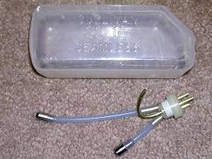 |
I'm partial to the '3 line' method. Fuel, pressure, fill/drain.
|
The vent/pressure is the top line. The fill/drain is the
front clunk (got to use the ARF tank clunk). The engine line with clunk
in the usual place in the back.
|
 |
 |
The trusty H2O test.
Plug up 2 holes, put the tank in water and blow and hope no bubbles appear.
Of course, it's easier to do it now than when the engine goes out in flight!
|
Tank mounted with the usual foam.
No need to secure it since I found that the center wing will put pressure
on the top of the tank and the back former will keep it from sliding back.
This was the easiest tank mounting that I've ever did.
Usually it's a pain to get those line through that small hole and then secure
the tank.
This was quick and easy.
The fuel and pressure lines are 6" and the fill/drain line is 9".
|
 |
|
NOTE: I'm using different fuel tanks that came with the ARF.
I'm using slant front tanks. The original tanks won't give you this problem.
I finished up on the tanks but I didn't have a good feeling on the second
tank. It felt a little tight near the fire wall. After pulling it back
out, one of the lines got pushed against the brass tubing and was cut.
With the 3 tube method, I had 2 of the tubes on top at about 10 and 2
o'clock and the third at 6 o'clock.
The bottom tube at 6 o'clock came through at a good angle through the
hole in the center of the fire wall. The other two tubes were too high
so I took the tank out and bent the 10 & 2 o'clock tubes down about
45 degrees. This was just right and when the tank was put back in, the
3 tubes aligned with the center hole in the fire wall.
There's enough room to see the tubes coming out and I made sure they weren't
twisted with each other and then connected them up to the muffler and
engine and let the fill/drain tubing hang down. I took the other tank out and did the same thing to it. |
 |
I used a foot long bit to drill through the fire wall and
next former for the throttle servo control rod.
|
We're raising the center throttle servo it
so it clears the outside servo.
I took one of the blocks for the fixed gears and cut it into 4 pieces, sliced
it down the middle and then I cut each part in half and sanded them. With
such small parts, I stayed away from the big power tools and used my scroll
saw.
Left: initial piece of wood- Right: final product.
|
 |
 |
A little epoxy and the throttle servo will now be 3/8"
higher.
|
There's now enough room to connect the throttle rod up
to the servo with the short side of the servo control arm facing to the
rear of the plane.
I used the white plastic tubing and the thin black control rods with a 'Z'
bend that were in the ARF box.
|
 |
 |
Several bends were needed to get around the boxy muffler.
A side benefit with this thin rod and the many bends was the throw of
the servo arm and engine throttle didn't have to be exact. On full throttle,
I get a slight bend of the wire but since the wire connects to the engine
throttle at almost a 90 degree angle to the rest of the rod, it acts like
a buffer.
|
Final check routing through the wires that
we'll use in the center wing. After the plane is put together, it may be
very difficult to adjust only one engine throttle so you may want to use
two channels.
I'm banking on the thin throttle wire and that 90 degree turn allowing me
to make some small adjustments by bending the wire.
I normally use a plastic clevis and adjust it at the engine throttle end
but that muffler just doesn't allow for such luxuries.
|
 |
 |
When I tried to put the struts in the spring air retracts,
the struts are a little too big in diameter, even when the set screw on
the retract is completely removed. I ended up putting some masking tape
7/8" from the end to protect the gray paint while I hand sanded the
exposed paint and some of the metal off.
I'm sure we'll have to do this again since it's unlikely that the length
of the strut is exactly what is needed. (good time to get some quality
bonding time with the other half by having her sand one strut while you
do the other one!)
|
GPS: general purpose stuff.
On the left is the foam cord I get at home depot that I'll use to put inside
the tires to keep them from going flat.
Center is homemade sanding sticks: white glue different grades to a paint
stick.
Right: 'magnetizer' from Rockler woodworking store: nice to magnetize all
those screw drivers to hold those small screw while putting them in tight
places.
|
 |
 |
The 3 hinges were already glued into the rudders on my ARF.
All I had to do was cut three slots in the vertical fin.
The slots are already under the covering so not too much to do here.
I made a flat side on one end of a popsicle stick and pushed the epoxy
into the slots.
Put a little oil on the center of the hinge pins and pushed the rudder's
hinges into the slots.
Nothing unusual on the control horns either.
The lower control rods are for the rudders.
The outer servos in the booms are for the rudders.
The clevises appear to be good quality so I just slipped on a piece of
fuel tubing first and then slid the rod from the rear into the black pre-glued
plastic tubes.
|
(the top servo in the picture is for the rudder).
The black plastic guide tube had to be cut back to the next former to
allow movement of the control arm.
For the rudder servo, I used Dubro's super strength servo arms.
After aligning the rudder to neutral and also first making sure the servo
arm is at neutral by turning on the receiver and transmitter, I used a felt
tip to mark the rod where it goes over the servo control arm.
I then put the usual 90 degree bend at the felt tip mark and cut off the
excess about 3/8" down.
I put the 90 degree bend at 3/4" out from the servo shaft and used
an E/Z link to hold it on.
|
 |
 |
As you can see, I'm getting max rudder movement. Needed if
one engine goes out.
(later, we'll paint all those white parts black so they don't 'stick
out' so much).
|
Normal stuff here.
Control horn on the horizontal stab.
Both sides of the stab are identical covering and airfoil so pick the best
side.
I put the control horn at a slight angle toward the boom to make a smooth
transition to the push rod.
|
 |
 |
Next, I connected the horizontal stab to both booms.
|
|
The screws are 1" long. Each ends of the horizontal stab have
pre-installed blind nuts. Test out the screws before connecting the booms.
One end of the stab on my ARF had the blind nuts at a slight angle (not
90 degrees to the rib) so the screws had to go in at an angle. You don't
want to force the screw in and cause the blind nut to come free: I've
done that before and the only cure is to cut the head of the screw off
so it can be fixed.
I cut the covering inside of the rudder, where the stab is attached, about
an 1/8" in. This allowed the stab to push that covering under it
so it makes a nice clean appearance and also unlikely to tear in flight.
The recesses on the outside of the rudder where the screws heads go are
easily seen
with the slight indentation of the covering. An x-acto knife was used
to put an 'X' cut at this spot. Both control horns mounted. I use a manual modelers drill: going
through balsa doesn't need anything more than 'hand' power. |
The top servo in the picture is for the elevator.
I taped the horizontal elevator to the rudder in a neutral position,
hooked up the clevis's to the control horns and, like the rudder, used
a felt tip to mark the push rod directly over the hole in the servo control
arm.
Bend it 90 degrees, put it all together with a E/Z link and she's 'good
to go'.
|
 |
 |
Testing the elevator:
Elevator in neutral position.
|
 |
Elevator in down position.
|
I cut a small notch in the former just behind
the center throttle servo using
a razor saw.
The 3 servo wires and 2 airlines (3 needed if you're not using Spring air
retracts and also installing brakes) come out of the center wing directly
over the servos.
I was concerned about these wires eventually/possibly getting entangled
with the servo arms. To prevent this, the wires and airlines go through
that notch and connect with the 3 servos on the 'retract' side where there
is lots of room. I used plastic ties to hold the servo wires together and routed them through
the same former where there already exists a large hole.
|
 |
 |
Pretty straight forward on this.
I used electric tape to tape the servo wire connectors to the wires coming
out of the center wing, inserted the center wing dowels into the booms,
aligned the wires and airlines in the slot we made, and put the 4 nylon
screws in.
Putting the booms on her nose made it easier to access the retract area
to make sure all the wires and airlines are in that notch and nothing
is being pinched.
For now, the retract and brake lines are just looped out of the center
hole of the center wing.
We'll cut them later for connecting to the air valves.
Leave several inches of air line sticking out of each boom so we can easily
connect them up later.
That 'rats nest' connecting to the receiver isn't too bad, considering
how much 'stuff' we're operating!
|
Checked out all the servos and all's working good.
|
 |
|


|
Drop tanks.
Figure I might as well paint them up so they are thoroughly dry
by the time we use them. Use 240 grit or finer to rough up the surface
of the plastic to give the surface some 'tooth' for the paint to stick
to.
First coat is primer.
Any of the spray paints at HD or Lowe's in a can will do, but we'll
need to use a fuel proof clear coat for the last coat.
Primer is important: it's virtually impossible to get a smooth coat
of paint without primer.
Second coat: Black.
As with the primer, it's best to put on several light coats than try
to cover it
in one coat (also, less likely for the paint to attack the plastic).
|
|
Notice: Questions
or statements regarding product quality and/or usage are solely the opinion
of the writer and not necessarily the opinion or recommendation of rcwarbirds.com
or rcwarbirds.com owner/webmaster. By asking a question you are giving
rcwarbirds.com or rcwarbirds.com owner/webmaster the right to post your
question and name on this page. Not all questions are answered or posted.
All questions and answers are copyright rcwarbirds.com |
BACK to REVIEWS
|
|
Become an RCWarbrids site supporter by making a donation.
|
$5.00 |
 |
$10.00 |
|
$15.00 |
|
$20.00 |
|
| |
|
|
|
|
